


The Most Common Problems With Residential Counterflashing

By Derek Hodgin, RBEC, RRO, PE, CDT.
Understanding problems with counterflashing and how to avoid them.
(Editor's Note: This article was originally published in the March 2020 issue of Interface)
Part of serving as an expert in construction litigation includes reviewing the applicable building code(s), manufacturer installation instructions, and accepted industry standards that were available at the time of construction—collectively referred to as the contractor’s instructions.1
Such a review is often associated with a building that has construction defects related to flashing. This article highlights four of the most common problem areas (in no particular order) associated with residential counterflashing installations and cautions how to avoid trouble.
Some of the examples discussed in this article may not fit the definition of what some readers would traditionally think of when discussing counterflashing, so a review may be helpful. Rather than being limited to metal installed on a masonry wall, the definition below better captures the broad use of materials used to prevent water intrusion, as discussed in this article.2
Counterflashing – Formed metal or elastomeric sheeting secured on or into a wall, curb, pipe, rooftop unit, or other surface to cover and protect the upper edge of a base flashing and its associated fasteners.
The concept of counterflashing is simple: a second (upper) layer of protection is provided to keep water from penetrating behind the first (lower) layer. If you are into analogies, it is like extending your pant legs over your rain boots. Your rain boots are the base flashing, and your pant legs are the counterflashing. If you were to tuck your pants into your rain boots, that would be a reverse lap, which would be a dysfunctional flashing detail—something we are trying to avoid.
Problem Area Number 1: Roof/Wall Intersections
In many cases, a technical deviation from the contractor’s instructions is considered to represent a defect such that a repair is alleged to be required, even when no visible damage and/or consequence has been documented; such can be the case with counterflashing conditions at roof/wall intersections. However, lack of attention to the overall function of intersecting materials at this location can be problematic, resulting in water intrusion and associated damages.
A close examination of the contractor’s instructions reveals inconsistencies that, if blindly followed, would violate accepted building enclosure principles, potentially resulting in dysfunction and damage. One example is the installation of side-wall flashing that is counterflashed with siding with an inadequate lap. For the purposes of this article, the components will be limited to composition shingles installed on a steep-slope roof, intersecting a wall that is clad with fiber cement lap siding, based on recent contractors’ instructions (e.g., 2000 or later).
2015 International Residential Code (IRC)3
Chapter 7 of the IRC includes requirements for exterior walls. The fiber cement siding section of the code requires that the contractor follow the siding manufacturer installation instructions. Chapter 9 of the IRC includes requirements for roof coverings. The composition shingle section of the code requires that the contractor follow the shingle manufacturer installation instructions. The specific references to the manufacturer instructions make them a code requirement, as if they were part of the code (Figure 1).
Figure 1 – Code requirements regarding manufacturer instructions.
Siding and Shingle Manufacturer Instructions
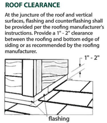
Figure 2 – Siding manufacturer detail.
Typical siding manufacturer installation instructions require the siding to be installed as much as 1 to 2 in. above the roof covering (Figure 2).4 Typical shingle manufacturer installation instructions require the vertical leg of the step and/or base flashing to be only 2 to 4 in. tall (Figure 3).5
Accepted Industry Standards
A summary of industry standard recommendations for the vertical height of step flashing is provided in Table 1. The National Roofing Contractors Association (NRCA) Roofing and Waterproofing Manual provides Detail ASPH-2, which requires the vertical leg of step flashing to be 4 in. tall.6 The Asphalt Roofing Manufacturers Association (ARMA) Residential Asphalt Roofing Manual provides Figures 10-1a and b, which require the vertical leg of step flashing to be 5 in. tall.7 The Sheet Metal Air Conditioning National Association (SMACNA) Architectural Sheet Metal Manual provides a detail that requires the vertical leg of step flashing to be 6 in. tall.8 The NRCA, ARMA, and SMACNA manuals are not referenced by the building code, but they are considered to represent accepted standards in the roofing industry (Figure 4).

Figure 3 – Shingle manufacturer detail.
|
Industry Group |
Reference Standard |
Detail/Figure |
Recommended Vertical Height of Step Flashing |
|
NRCA |
Roofing and Waterproofing Manual (5th Edition) |
Detail ASPH-2 |
4 in. |
|
ARMA |
Asphalt Roofing Residential Manual |
Figures 10-1a and b |
5 in. |
|
SMACNA |
Architectural Sheet Metal Manual (6th Edition) |
Figure 3-23 |
6 in. |
Table 1 – Industry standard recommendations for the vertical height of step flashing.
Avoiding Problems
The most important aspect of any constructed assembly is its ability to function as intended. In the case of exterior wall assemblies, the intent of the building code is to provide weather protection. Simply put, exterior walls need to keep the weather on the outside of the building. A wall that allows water to penetrate and cause damage to moisture-sensitive components (i.e., wood-based components such as wall sheathing, wall framing, roof deck, etc.) is dysfunctional and would require repair.
At the roof/wall intersection, the siding and underlying weather-resistant barrier (WRB) would serve to counterflash the vertical leg of the step and/or base flashing. Because accepted water management principles for exterior walls require a minimum 2-in. lap of moisture protection layers, it is clear that if the most extreme manufacturer instructions for both siding and roof shingles are followed, as required by the residential building code, problems could result. Specifically, installing step flashing with only a 2-in. vertical leg would not allow sufficient overlap of the siding to achieve the desired 2-in. lap. In this situation, if a gap of 2 in. were provided between the roof covering and siding, pursuant to the siding manufacturer instructions, there would be no lap at all!
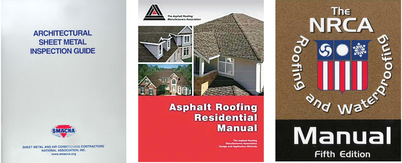
Figure 4 – Accepted industry standards.
To avoid problems at this location would require a step and/or base flashing height of at least 4 in. This would allow a 2-in. lap to be accomplished, even when complying with the siding manufacturer requirement of a 1- to 2-in. gap above the roof covering. However, many architects, contractors, and building owners do not like the large gap of exposed flashing between the roof and the siding. Standards referenced above should focus on the amount of overlap rather than the height of the base flashing. It would be best to limit the gap to 1 in., resulting in a more desirable 3-in. lap for the siding to counterflash the step and/or base flashing. Placing the siding closer than 1 in. from the roof covering could result in moisture damage along the edges of the siding. It is typically desirable to follow the most stringent requirements when able to do so; it will typically result in the most durable assembly.
Problem Area Number 2: Brick Chimney Flashing
Brick chimneys are a common feature on residential structures. Unfortunately, improper metal counterflashing on brick chimneys, just above the roof, is almost as common as brick chimneys. Even though brick has been around for a long time, we seem to forget about the details that are necessary for long-term performance. One of the most important components of brick construction is proper flashing to manage water. Even brick will break down when sufficiently exposed to elevated moisture conditions over prolonged periods.
The most common defect at this location is installing surface-mounted counterflashing on the side of the brick chimney (Figure 5). Sealant may or may not be installed along the top of the counterflashing. This detail will only be effective in rain events that are light and/or of short duration. It does not take a significant rain event to saturate the brick chimney sufficiently for water to migrate behind the counterflashing, potentially causing water damage to the roof deck, roof framing, or the interior of the building (Figure 6).
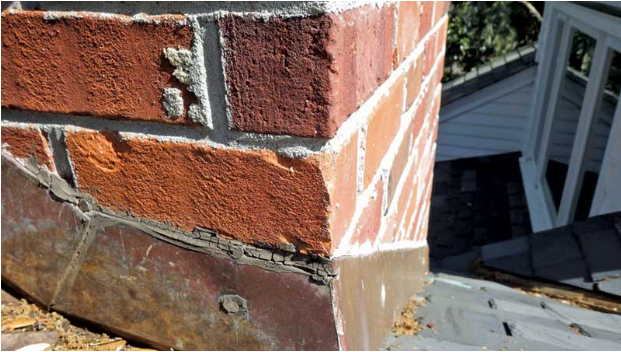
Figure 5 – Typical surface-mounted flashing.
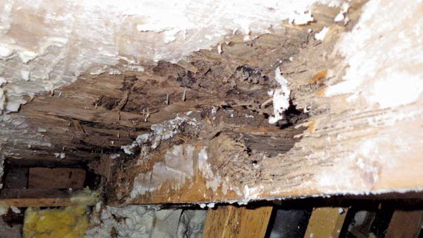
Figure 6 – Water-damaged roof deck at chimney.
2015 International Residential Code (IRC)3
Section R1003.10.1 of the IRC indicates that “Through-flashing and weep holes shall be installed as required by Section R703.” It is amazing that this has actually been a building code requirement since 2006, because it is rarely ever observed, at least in most of the buildings investigated by the author. However, the author acknowledges that performing forensic investigations of nonperforming buildings results in a biased data set. Hopefully, there are a large number of chimneys constructed with proper, code-compliant flashing details that function well for many decades; those chimneys are not typically included in a residential construction defect case.
Shingle Manufacturer Instructions
Typical roof shingle manufacturer installation instructions do not address new construction of masonry chimneys with through-flashing, as required by the building code. Rather, most instructions depict an existing masonry chimney, with no existing flashing. The instructions describe the installation of step and/or base flashing and counterflashing (aka cap flashing) that is inserted into reglet(s) that are cut into the brick a minimum of 1-in. deep (Figure 7). Most instructions include details for “stepped” counterflashing that is set into reglets cut into horizontal bed joints, and continuous counterflashing that is set into a reglet that is cut parallel to the roof surface.5
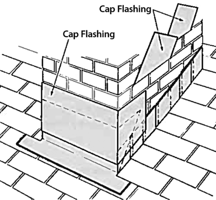
Figure 7 – Manufacturer counterflashing details.
Accepted Industry Standards
The referenced NRCA manual provides detail ASPH-1, which depicts a continuous reglet (aka raggle) around the chimney, above the apron and step flashing (Figure 8).
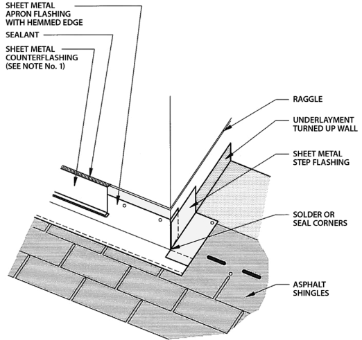
Figure 8 – NRCA Apron Flashing.
The ARMA manual devotes nearly five pages of text and details related to chimney flashing. Figure 10-14 shows the cross section of the counterflashing details, while Figures 10-15 and 10-16 show isometric views of the installation of counterflashing around the chimney. Unfortunately, Figure 10-14 does not incorporate the “best practices” described above. Specifically: 1) the flashing is depicted to be inserted into a horizontal reglet, not sloped; 2) the counterflashing is depicted to be installed vertically, in contact with the step flashing, without a capillary break; 3) the counterflashing terminates without a hemmed drip edge; and 4) the minimum 2-in. overlap between the counterflashing and step flashing is not identified (Figure 9).
Figure 4-18 of the The SMACNA Architectural Sheet Metal Manual9 shows isometric counterflashing details that are similar to the ARMA details, but does not include the cross-section detail.
The NRCA, ARMA, and SMACNA manuals are not referenced by the building code, but they are considered to represent accepted standards in the roofing industry.
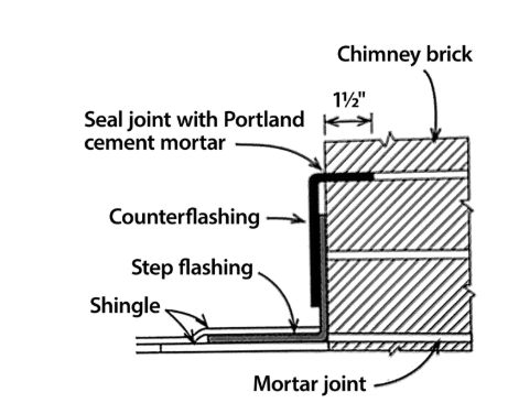
Figure 9 – Industry detail lacking “best practices.”
Other References
The Brick Industry Association (BIA) Technical Note 19B – Residential Chimneys: Design and Construction10 includes Figure 7, showing a general isometric depiction of chimney counterflashing, with no specific details. The most current version of this Technical Note appears to be 1998. However, BIA published a July 2005 “Brick Brief” with the title of “Flashing Chimneys.”11 Figure 2 of this two-page document depicts through-flashing, consistent with the 2006 version of the IRC, released a short time later (Figure 10). The details of the counterflashing lack “best practices” as described previously.
The Journal of Light Construction (JLC) Field Guide to Residential Construction, A Manual of Best Practice, Volume 1,12 includes Figure 3-81, which illustrates through-flashing around the brick chimney, extending over the base and step flashing, and serving as counterflashing. While the author believes this detail is functional, it may not be realistic or easily constructed. This opinion is based on the throughflashing and counterflashing being the same piece, which would be difficult to construct and has not been observed in any investigation of modern residential structures. Again, because of the forensic nature of the author’s experience, this detail may be common in chimneys that are never observed because they work so well.

Figure 10 – BIA “Brick Brief” counterflashing detail.
Avoiding Problems
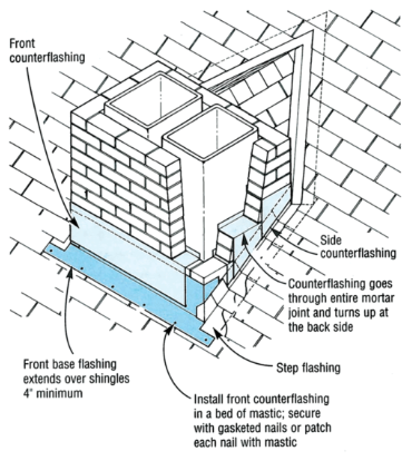
Figure 11 – JLC flashing detail.
The most important aspect of the counterflashing on a brick chimney is the ability to intercept the water that migrates toward the building from above. Ideally, through-wall flashing should be installed to intercept this water, as intended by the building code. The through-wall flashing would extend over the top of the base and/or step flashing to serve as counterflashing (Figure 11). This is the most robust solution, because water is able to penetrate completely through the outermost course (or wythe) of brick and still be collected and directed back to the exterior, just above the roof base and/or step flashing.
Alternatively, the counterflashing could terminate into a deep reglet cut into the brick veneer. To improve the function of this detail, the reglet should be cut at an angle to drain water. Additionally, the edge of the flashing that is inserted into the reglet can be folded to create a compression fit, held in place with lead wedges and topped with a urethane sealant joint. The flashing should extend away from the chimney, past the base or step flashing, before taking a sharp bend downward to create a capillary break, an air space that will not allow capillary suction of water from below. The base of the counterflashing should include a hemmed drip edge to manage the water (Figure 12). The minimum depth of the reglet should be 1 in., but 1½ in. is preferred.
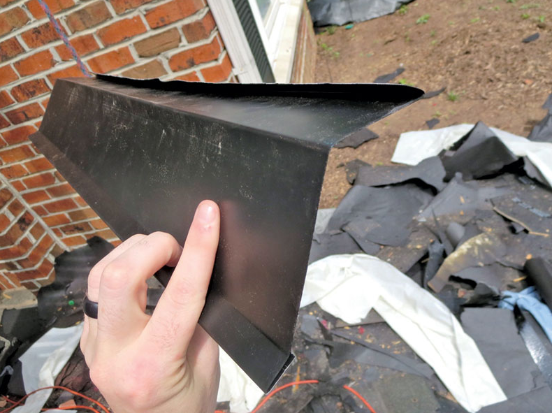
Figure 12 – Profile view of best-practices counterflashing.
Problem Area Number 3: Eave Flashing
Based on the author’s experience, this is one of the most common residential roof flashing defects of all time. The defect consists of the improper integration of the roof underlayment and the metal drip edge, collectively referred to as the eave flashing (Figure 13). If the roof underlayment does not lap properly over the metal drip edge, water is potentially allowed to penetrate to the roof deck, fascia, and sub-fascia areas, which typically include untreated wood that is susceptible to water damage (Figure 14).
The cause of the problem seems to be partly associated with the installation of “toe boards,” consisting of 2- x 4-in. boards nailed along the eave to provide a safe walking edge, as well as a “catch” for tools, shingles, or anything else that may potentially slide off of the roof during construction. Unfortunately, when the boards are removed, the roof deck is either void of underlayment over the last 31/2 in., or unsealed nail holes are left in the roof shingles, depending on the sequencing of the work. Another cause of this defect is simply the improper sequencing of the work and a general lack of understanding regarding the importance of this detail, even though this information is printed on most bundles of roof shingles.
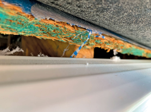
Figure 13 – Improper eave flashing.
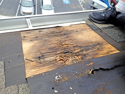
Figure 14 – Water damage at roof eave.
2015 IRC
Chapter 9 of the IRC includes Figure R905.2.2(1), which depicts the proper installation of a metal drip edge, underlayment, and asphalt roof shingles over a wood deck (Figure 15). The figure shows the metal drip edge properly integrated below the roof underlayment along the eave and over the underlayment along the rake.
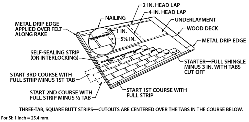
Figure 15 – Proper eave flashing.
Roof Shingle Manufacturer Instructions
Typical roof shingle manufacturer installation instructions include a graphic depiction of the roof eave, clearly showing the proper integration between the roof underlayment and the metal drip edge.
Accepted Industry Standards
The NRCA is the source of the previously referenced figure in the IRC. However, Detail ASPH-4 in the Roofing and Waterproofing Manual provides a blow-up of the eave that more clearly depicts the proper integration between the metal drip edge and the roof underlayment. An alternative detail is provided that depicts “ice dam protection membrane” installed over the roof deck, extending over the fascia, and covered by the edge metal flashing. This is acceptable since the water is precluded from migrating to the wood components below.
The ARMA manual includes Figure 3-5, which depicts the application of drip edge at the rake and eaves. The text in this manual recommends that the metal drip edge extend approximately 3 in. back from the roof edge. This recommendation is sufficient to allow a proper (2-in. minimum) lap of the roof underlayment.
Avoiding Problems
he most important aspect of eave flashing is sequencing the installation of the roof deck, subfascia, roof underlayment, fascia, metal drip edge, and flashing tape/ice and water shield in a way that results in a weather-lapped condition that does not allow water to penetrate the roof assembly. It is also important that the face of the eave flashing should extend into the gutter to keep water from getting behind it and rotting the fascia board. These are not difficult details to accomplish, but this seems to be one of the most common roof flashing errors in residential construction. Following the abundance of published details in the code and elsewhere would avoid problems.
Problem Area Number 4: Double Layers of WRB
This issue was introduced when the 2000 IBC required the installation of two layers of WRB behind stucco. Adhered stone veneer products also require a double layer of moisture protection. The problem is that it has not been widely recognized that directing water between the two layers of WRB, as described by the code and prominent WRB manufacturers, can overwhelm the wall and cause significant damage, even when technically meeting the code.
The concept of the two-layer system is that the outer layer (typically asphalt-saturated felt), which is in contact with portland cement stucco or mortar used with adhered stone, is a sacrificial layer that serves as a bond breaker. The water absorbed by the outer layer will cause the felt to swell and expand, resulting in a gap to facilitate drainage. This concept works well when the water intrusion is incidental in volume. However, when water is directed between the two layers of WRB, the wall assembly is overwhelmed and significant damage can result.13
2015 IRC3
Section R703.7.3 of the IRC includes the requirement for the installation of two layers of WRB behind stucco, as follows:
The individual layers shall be installed independently such that each layer provides a separate continuous plane and any flashing intended to drain to the water-resistive barrier is directed between the layers. [Emphasis added.]
WRB Manufacturer Instructions
The 2017 DuPont Tyvek Installation Guidelines14 for stucco and direct-applied stone repeat the IRC requirement described above.
The Fortifiber Jumbo Tex “instructions for Installing Water-Resistive Barriers and Flashing in a Two-Layer Stucco Application”15 states:
An outer layer of Jumbo Tex is now installed over the first water-resistive barrier layer in weather-board fashion, following the same requirements for overlaps and fasteners. However, this layer is not integrated with the window flashing, but is instead installed over the integrated flashing and first water-resistive barrier.” [Emphasis added.]
As described above, the WRB requirements described by the IRC and manufacturer installation instructions will work when the water intrusion is incidental. However, when water is directed between the layers at areas in a concentrated manner, such as roof/wall intersections, windows/doors, balconies, etc., the inner layer of WRB will not be able to manage the water, and damages will result. This condition has now been documented on numerous stucco and stone-clad buildings.
Accepted Industry Standards
ASTM C1063, Standard Specification for Installation of Lathing and Furring to Receive Interior and Exterior Portland Cement-Based Plaster,16 is referenced by the IRC. This standard defines “water-resistive barrier” and “water-resistive barrier system,” but it does not describe the installation of these components.
The Portland Cement Association (PCA) Plaster/Stucco Manual17 references the 2000 IBC requirement of two layers of Grade D (water-resistant, but vapor-permeable) paper be placed over plywood sheathing that is to receive lath and plaster. However, no installation details are provided.
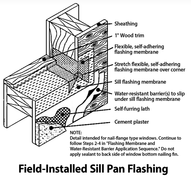
Figure 16 – Proper integration of WRB layers at a window.
Other References
A contractor guidebook called Builder’s Guide to Stucco, Lath & Plaster18 is one of the few references that describe the need to properly integrate the two layers of WRB to keep the water on the outside of the outermost layer. Specifically, Figure 2-14 in this book indicates that the two layers of WRB are to be integrated behind the windowsill flashing, precluding the water from penetrating between the layers, as allowed by the code and WRB manufacturers (Figure 16).
Avoiding Problems
It is important to properly integrate the two layers of moisture protection to keep the water on the outermost surface whenever possible. This is particularly important in areas where concentrated water intrusion can occur. Pay close attention to areas where the drainage plane is interrupted to find locations of potential water intrusion. For this specific issue, following the code and/or WRB manufacturers can (and has been documented to) result in significant damages.
Conclusion
It is more important to understand how building assemblies work than to blindly comply with applicable contractors’ instructions. Always follow the path of water that will penetrate the skin of the building (regardless of the cladding type) and reach the moisture protection layers that are needed to protect the integrity of the building. Make sure that no easy paths exist that allow water to reach materials that are vulnerable to damage. Also, make sure that the components that are being relied upon for moisture protection are installed in a manner to perform long-term. This may require design improvements that are not required by the code, such as the installation of more robust materials and/or creating an air space via battens or a drainage mat. Ultimately, building function should always win out over following minimum requirements that may be lacking in durability.
Learn more about IIBEC in their RCS directory.
Original article source: IIBEC
Recommended For You
Unique Use of Polyprene®
Read More ...
Roofing Shingle Home Styles: The Colonial
Read More ...
Tested to Withstand Category 5 Wind Speeds
Read More ...


Comments
Leave a Reply
Have an account? Login to leave a comment!
Sign In